Wednesday, October 19, 2011

Making a tachometer!

Just got my PIC16F628A in the mail today.  This will be my first time using a chip other than the 16F887.  I found the datasheet here PIC 16F628 and started looking over the features.  Internal Oscillator, 16 I/O ports, comparator, PWM, and a couple timers.  YAY! 
PIC16F628A Pinout

The first project I am going to be doing with it is a digital tachometer.  A signal will be generated by a hall effect sensor and magnet, translated by the PIC into RPM, then displayed on a four 7-segment displays. Use it for a bike or maybe find a way to hook it up to my car.  
Board for the 4 7-Segments.  I'll
add schematic and design if anyones interested.

I started by getting the pinout and hooking up  power (Vdd) and ground (Vss).  Then looked up how I was going to connect the oscillator.  I want pretty good accuracy and the internal oscillator is effected by temperature so I decided to use a 4 MHZ crystal connected between osc1 and osc2, along with two 68pf caps to ground.  Also put a 10uf cap from +5 to ground near the supply and a .1uf cap across Vdd and Vss close to the chip.  After that, I hooked up the PICKIT to power and ground, and connected the PGD (data) and PGC (clock) to the chip.  Loaded up MPLab and it recognized it right away!  After that I hooked up my 7-segment pcb.  The individual segment LEDs are controlled by PORTB, (a=0, b=1, c=2 etc..) while the digits are turned on in off with the lower nibble of port a. (digit 0 = 0, digit 1 =1, etc)  Works great but take note that I used PNP transisotors for current supplement to the LEDs, so the logic is reversed.  (A 0 on the port turns the LED on, while a 1 on the port turns it off)

Wiring is kinda messy.  7 Segment is a custom PCB
I designed and printed out.   It has 8 wires for the segments
and 4 wires for Digit select.  Plus one 5V power wire. 


Saturday, September 17, 2011

LED 5x7 Matrix

So, after getting my PICKIT all set up I decided to put together a small 5x7 Display.   The LED matrix is from an banner board I found in the trash,  with all of the original traces dremaled out and my own wires connected. Was alot of work considering I could get a new one prewired for like $2.00 online, but I didn't know that at the time. Its controlled by the PIC16F887 which is overkill for sure but its the only chip I have right now.
Schematic for display.  Or just buy one.                    
                                        
The display does a couple simple patterns then displays the message "PARTY!" Both columns and rows are activated by a low (0V) signal using PNP transistors. I have the code and schematic but I can't find my memory stick right now so I'll have to upload it later.

Here is a youtube video I put together for it. 

Friday, August 26, 2011

Lets Get Programming!

Got the my Pickit 3 to wired up and talking to my chips today.  Wiring was really simple but had a bit of trouble initially getting it to recognize my PIC16F887.  Took me awhile to figure out why I was ID errors trying to connect, but apparently I accidently specified in MPLAB that I was using a 16F877 and not the 16F887.  Also set up using the 16F887 internal oscillator for the first time.

Diagram for hooking up PICKIT

PIC16F887 with simple LED blink test program. 

Thursday, August 4, 2011

5V 1A Linear Power Supply

5V 1A  Linear Power Supply

        Just got through putting together a new 5V supply to use with my digital projects.  The adjustable supply I have is fine, but thought it would be nice to have a dedicated supply for TTL and micros.  Its a simple circuit but I would prefer to not have to breadboard it all the time and have it take up precious work space.  Decided to slap this supply together quickly with some extra parts that I had laying around.

'Parts List'
These are not ideal, but what I had laying around.
click to enlarge
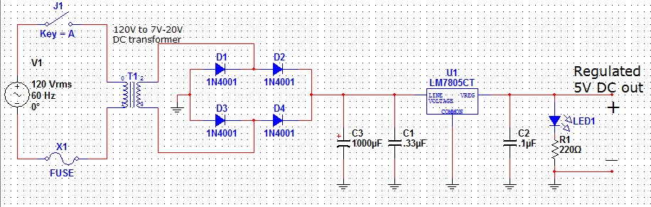
'Schematic for 5V/1A Linear Regulator'
click to enlarge
!note! should have a reverse biased protection
 diode going from Vin to Vreg (pins 1 to 3)


Testing unloaded AC output
 of a transformer.  The grey box is a
little fused AC outlet I built for testing.
       The supply is based off the 7805 linear regulator. (datasheet) It is a simple circuit and the regulator portion was pulled straight from the datasheet.  120V/60hz AC from the wall is reduced down to 10.7V/60hz AC  then rectified through a full-wave diode bridge.  The diode bridge doubles the frequency to 120hz, as well as drops the voltage an additional 1.4V. This signal is then fed into a filter capacitor, which because of the time delay of the charge and discharge, helps to produce an approximate DC voltage level with some ripple on it. This is in turn fed into the 7805 regulator which produces a clean 5V DC on the output.


    A switch and fuse were added to the 120V side of the transformer, as well as a power-on LED on the output which also helps drain any stored up charge left on the large filter capacitor. Wouldn't want the cap to discharge into some circuit after the power is assumed to be off.

Simple block diagram of different stages.
     I used a 1 amp fuse on the 120V side of the transformer cause that was all I had, but I'm pretty sure about a 250mA fuse is needed and here is why. The transformer reduces the voltage from about 120V to approximently 10V for a reduction factor of 12.  (120V/10V = 12)  This means that the amperage should be reduced by a factor of 12 going from the low voltage side to the high voltage side.  So ideally if the regulator can only use 1A total. (I'm not factoring current draw from the caps charging) then the amperage seen from the high voltage side should only be 1A/12 = 120mA.  So am I correct in thinking a 250mA slow-blo fuse would be safe?

Wish I had a working oscilloscope for testing.
Voltage dropped to 4.99V @ 800mA.  
       Although not all the values of the components are ideal, I have tested the circuit up to 800mA and it holds the voltage up to about 4% of a no-load condition.   I didn't calculate the exact value of the filter cap to give 10% ripple, and instead just followed the rule of thumb of 1000uF for every 1A of power.  Initially I was having problems  with the voltage dropping significantly whenever a load of more than 500mA was applied, but it turns out the "unrated" transformer I was using couldn't keep up and was dropping the voltage fed into the regulator to about 6V. The 7805 needs about 2V of headroom to function properly, so I swapped out to a beefier transformer and its voltage fine now.


It was a tight fit with the new
transformer but I got it all in there.
Love me some hot-glue.
        I will probably end up building another 5V supply, but this one will work out fine for now.  I would like to order all new parts from digikey for the build.  There are a couple improvements to add as well, namely using two 1000uF capacitors with a small 2ohm/5W resistor between them. (T-Configuration?)  This will help limit the initial rush of current when filter caps are charging, putting less stress on the entire system.  Also try and get some beefier rectifier diodes and a rated transformer.   I also forgot to add a reverse biased diode from IN to OUT on the regulator to help prevent damage from reverse current flow into the supply. Next time I'll probably build everything on a PCB too and maybe add some transistors to supplement the output current of the regulator.

        All in all the build went pretty smoothly and I finished it in about a day. Originally I was going to have the whole thing built on a single board with "headers" so I could plug directly into a breadboard but I think its better with the banana plug outputs.  Frees up breadboard space, and the plugs will still go directly to the power rails of the breadboard.  It hasn't been used extensively yet, so I'll report back if anything  goes up in smoke.


LED with resistor and wire "heatshrinked"
Using the Dremal to remove metal burrs. 

Saturday, July 23, 2011

Moving from MPLAB 8 to MPLAB X

Just got my PicKit 3 in the mail, so going to get cracking on some new micro projects.  (probably end up doing a cycle timer for lights and fans)  Just downloaded the new Beta for MPLAB X so we will see how it compares to MPLAB 8.   Also want to post my results for some other projects I have completed, mainly the Pic based Dice and an update on the new binary clock I put together.  Also have some odds and ends to put up like my little binary to 7-seg display and 7-seg micro breakout board I put together.   Lots to do....

Wednesday, October 6, 2010

First Youtube Upload.

Do I posted my first video to youtube showing the Binary Clock I put together awhile ago. Theres an excellent description of the schematic at Binary Clock Tutorial. 

The clock is driven by the 60hz from the wall, which is divided down to 1hz to run the seconds counter. (which then goes on to drive the minutes and hours)  AND gates reset the counters when they count to a certain value ( such as sixty "0011 1100" ).  That reset signal also pulses the next counter in line.   Just read over the page I linked to  cause it has all the info there.  

The video I posted is short n shitty cause I ran outta batteries on my camera so I don't really show it off long or explain how it works.  It'll do tho plus I'm going to start building my own here soon that I designed and I'll put more effort into that. 

Anyways, heres the video!

First Post, Trying shit out.

Alright so lets see how this goes.  I'll post some good electronics forums.

 dutchforce.com
electro-tech-online.com

Try putting on some videos.


And lets's see how it goes.....